
Industry trends
Focus on semiconductor electrical performance testing
location:Home > News > Industry trends
Precise PL series narrow pulse current sources can be applied to VCSEL and other test scenarios that require narrow pulse excitation.
PL Series devices have two channels:
①, constant current pulse excitation source, and can simultaneously measure the voltage at both ends of the device under test;
②, Pulse current measurement channel, especially suitable for measuring pulsed optical power by means of external PD;
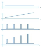
PL series equipment can output the following waveforms: the amplitude, step value, pulse number, etc. of the waveform can be programmed.
①, DC constant current;
②, DC scanning current;
③, pulsed direct current;
④, pulse scanning current;
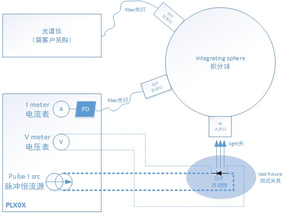
The block diagram of the test using the Precise PL series narrow pulse LIV test system is as follows: it mainly consists of PL series equipment, dedicated connecting wires, test boards, integrating spheres, lasers to be tested, and light receiving PDs. VCSEL lasers generally have a large output optical power, while PDs have low received power, and an integrator is needed to attenuate the optical power. At the same time, the reflection characteristics of the integrating sphere make the laser system not very sensitive to the incident angle of the laser light.
The equipment outputs the following signals: LD+, LD-, S+, S-, PD+, PD-, among which LD+, LD- are constant current source output excitation signals, S+, S- are voltage measurement signals of the device under test, PD+, PD- is the external PD measurement signal.
In order to ensure the quality of signal output, PL series devices need to use special connecting wires customized by Proceeds. At the same time, the connection from the test board to the device under test should be minimized. It is best to solder the device directly to the test board or use a socket.
In order to ensure the accuracy of the voltage measurement of the device under test, S+ and S- need to be short-circuited to LD+ and LD- on the pins of the device under test. Please be sure to connect S+ and S- to the pins of the device under test, and do not directly Feel free to short-circuit on the test board.

 Email
Email
 Contact
 Inquiry
 Home
Home
